Introduction
This guide is written for fabricators, project engineers, and procurement teams who need CNC machined features on fabricated assemblies. It covers why welding creates a machining need, what tolerances fabrication can and cannot achieve, the six features most likely to need precision machining after fabrication, and how to plan the job so that both processes work together efficiently.
Summary
Key Takeaways
- Welding distortion is the root cause. When a weld pool cools and contracts, it pulls the surrounding metal with it. The result is a fabricated assembly that has moved, sometimes by a millimetre or more, from its intended geometry. This movement is normal and manageable if it is planned for. It becomes expensive if it is not.
- Fabrication and CNC machining hold very different tolerances. As-welded fabrication typically achieves ±1.0–2.0mm. CNC milling and turning under standard defaults achieves ±0.02–0.1mm. The gap between these two figures is why many functional features need machining after fabrication; the fabrication process simply cannot hold the tolerance the feature requires.
- Six features come up again and again. Flange faces, bearing housings, pin and bushing holes, base plates, threaded holes, and match-machined assemblies are the most common handoff points between fabrication and precision CNC machining. Each one has a specific reason why the as-fabricated condition is not good enough.
- Machining allowance must be designed in from the start. If you do not leave extra material on faces and bores destined for machining, the weld distortion may consume the available stock, and the machinist has nothing to cut. Adding machining allowance at the drawing stage costs almost nothing. Fixing the problem after the fact costs significantly more.
- Match-machining after welding is often the right answer. For assemblies where two or more components must align precisely, it is usually better to weld first, let the assembly settle, and then machine the critical features together in a single setup, rather than machining each piece separately and hoping the weld holds everything in position.
- Australian welding and fabrication standards define the baseline. AS/NZS ISO 3834 sets quality requirements for fusion welding; AS/NZS 5131 governs structural steelwork fabrication and erection. Understanding which tier applies to your project tells you what documentation your fabrication supplier needs to provide.
1. Why Fabrication Creates a Need for CNC Machining
Fabrication, welding, laser cutting, plasma profiling, press braking, is designed to produce complex shapes quickly and economically from stock material. It is not designed to hold tight dimensional tolerances on specific features. For most of a fabricated assembly, that is fine. For certain features, it is not.
Welding Distortion
Distortion is the most common reason a fabricated assembly needs post-weld CNC machining. When a weld pool solidifies, it contracts. That contraction pulls against the surrounding, cooler, more rigid parent metal, generating residual stresses that cause the workpiece to move. The four main types of movement are:
- Longitudinal shrinkage: shortening along the weld run
- Transverse shrinkage: pulling the joint faces together across the weld
- Angular distortion: rotation of the plates around the weld line, lifting edges and creating a V-shape across the joint width
- Buckling: thin plates can buckle or bow under the compressive stress introduced by welding
For most structural applications, this level of movement is acceptable. The assembly still does its job. But when a bore, a face, a flange, or a mounting plate needs to sit in an exact position relative to the rest of the assembly, that movement has consumed the available tolerance, and the feature needs to be machined back into position after welding is complete.
Thermal Cutting Edge Quality
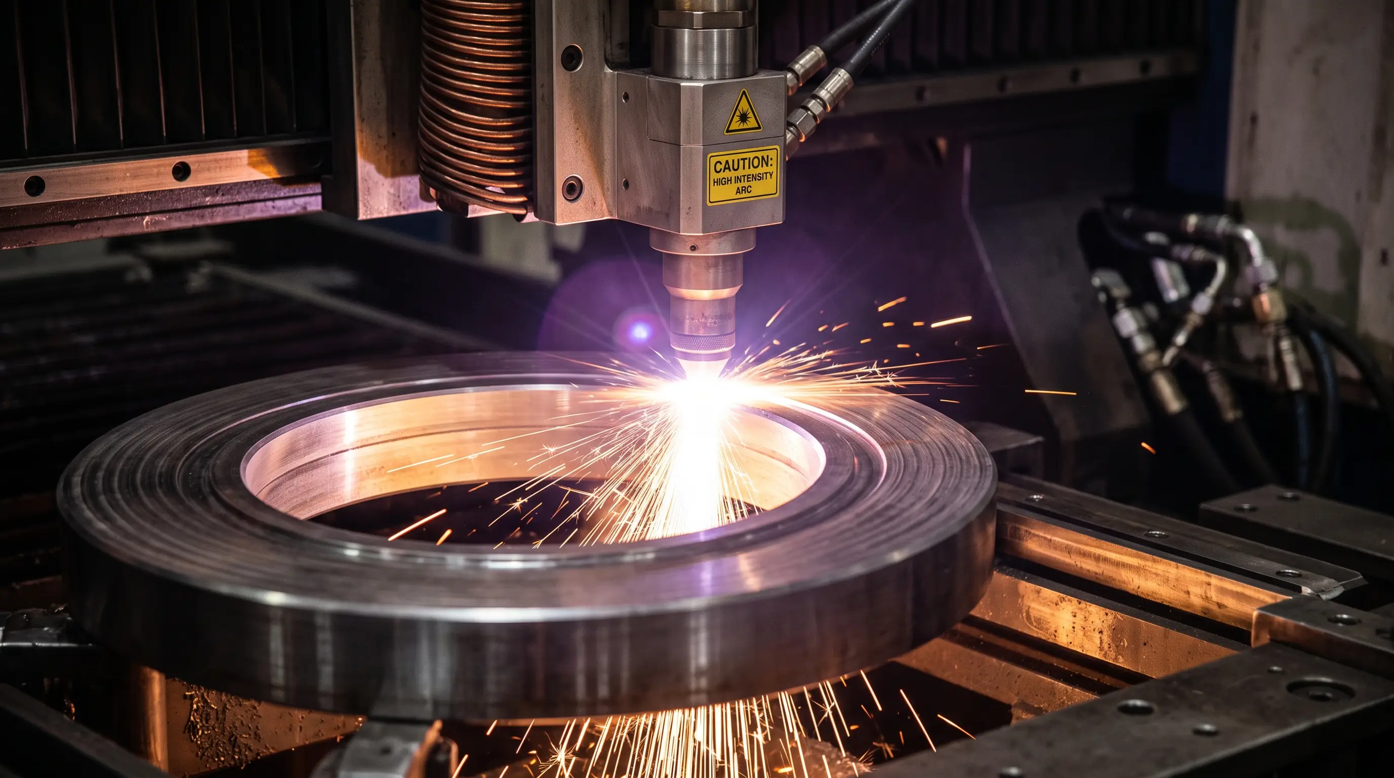
Laser and plasma cutting produce efficient, accurate profiles, but the cut edge itself is not suitable for precision functional use. The heat-affected zone (HAZ) along the cut edge changes the material properties locally; the edge has some taper from top to bottom; and the surface left by the plasma arc or laser beam is not flat or square enough for sealing faces, running fits, or press-fit features.
This is by design. Thermally cut edges are produced for edges that will be welded, painted, or fastened with clearance bolts. For any edge or face that needs a controlled dimension or surface quality, a sealing face, a bore diameter, a press-fit location, that feature gets machined after cutting, not used as-cut.
2. The Tolerance Gap: What Each Process Can Actually Hold
Understanding the tolerance each process produces makes it immediately clear why some features need to move from fabrication to CNC machining. Here is a practical comparison:
Fabrication Tolerances
- Sheet-metal bending: typically ±0.2–0.5mm on bend angles and dimensions
- Plasma and laser cutting: typically ±0.1–0.5mm on profiled dimensions (better at the bottom of the range with laser; plasma is coarser)
- As-welded fabrication without post-machining: typically ±1.0–2.0mm across an assembly
CNC Machining Tolerances
ISO 2768-1 defines four general tolerance classes for linear dimensions. For a nominal dimension in the 30–120mm range:
- Fine (f): ±0.15mm, tighter than most fabrication, suitable for non-critical machined surfaces
- Medium (m): ±0.30mm, the standard CNC machining default for general work
- Coarse (c): ±0.80mm, approaching the lower end of fabrication tolerance, rarely specified for machined features
- Very coarse (v): ±1.50mm, equivalent to as-welded fabrication; not a useful machining target
In practice, CNC milling and CNC turning routinely hold ±0.02–0.1mm under a standard ISO 2768-mK default, well inside the Medium class, and can achieve ±0.005–0.01mm on critical features with appropriate process controls. The gap between ±1.0–2.0mm (as-welded) and ±0.02–0.1mm (CNC machined) is the reason post-weld machining exists.
3. Six Handoff Points That Need CNC Machining After Fabrication
These are the features that come up repeatedly when fabricated assemblies arrive at a CNC machine shop. Each one has a specific reason why the as-fabricated state is not sufficient.
1. Flange Faces
A flange face that is not flat cannot seal. For pipe flanges, pressure vessels, and hydraulic connections, the gasket relies on even compression across the entire seating face. A weld-distorted or thermally cut face has peaks and valleys that create leak paths under pressure.
Post-weld machining options depend on the flange type:
- Flat-face and raised-face flanges: a single-pass facing operation removes all surface irregularities and brings the face to the specified Ra roughness, typically a light serrated finish of 3.2–6.3µm Ra for resilient gaskets
- Ring-Type-Joint (RTJ) flanges: require a precisely machined groove to a tight depth tolerance; an undersized groove prevents the seating ring from bedding correctly, and an oversized groove loses the sealing force the ring depends on
2. Bearing Housings and Bores
A bearing needs to sit in a housing that is round, cylindrical to within a defined tolerance, and sized to the correct ISO fit class. The bore diameter determines whether the bearing outer race is a press fit, a transition fit, or a running fit, and a bore that is 0.2mm oversize can mean the bearing spins in the housing rather than remaining fixed.
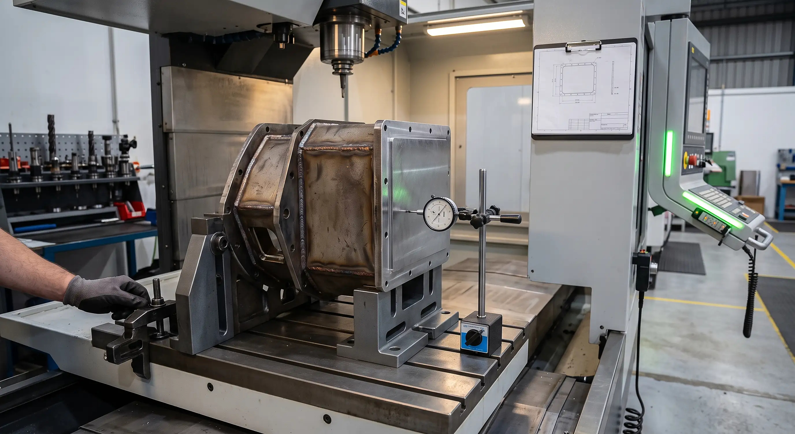
A welded bracket cannot produce this bore. The welding process moves the bracket; the as-welded hole size and roundness are not controlled. The bore is always bored or reamed out on a CNC mill or lathe after the fabrication is complete and, where needed, stress-relieved. The machining operation machines the datum surfaces and the bore in a single setup, ensuring they are perpendicular and concentric to each other.
3. Pin and Bushing Holes
Pin holes in fabricated arms, brackets, and linkages need to be in exactly the right position, and sized to the correct clearance or interference fit for the pin or bushing being installed. A hole that is slightly out of position can prevent assembly or cause binding in service. A hole that is oversized allows the pin to float, creating impact loads and accelerated wear.
- Thermally cut or punched holes have too much size variance, taper, and edge roughness for a controlled pin fit
- Reaming after drilling brings the hole to a precise diameter with a defined surface finish, typically Ra 0.8–1.6µm, for a reliable pin-to-bore relationship
- Match-machining pin holes in pairs (drilling both halves of the joint in the same setup) ensures alignment without relying on each piece being individually machined to a tolerance
4. Mounting and Base Plates
Equipment mounted on an uneven base plate transmits vibration, generates fretting corrosion on the contact faces, and can introduce twist into sensitive machinery. A precision base plate, machined flat, parallel, and perpendicular to the design datums, provides a stable, defined foundation.
Post-weld base plate machining typically involves:
- Stress-relieving the welded assembly before finish machining, to allow residual weld stresses to redistribute without distortion after the machining operation
- Rough facing to remove the bulk of material and expose a consistent, clean surface
- Finish facing to achieve the target flatness, parallelism, and surface finish
5. Threaded Holes and Machined Counterbores
Threads are inherently a machining operation. Whether tapped, thread-milled, or single-point turned, a thread needs to be cut to a defined pitch diameter and tolerance class (e.g. M12 × 1.75, 6H) for a reliable fastener engagement. A thread that is too loose allows the fastener to work under vibration; one that is too tight will cross-thread during assembly.
Counterbores, the recessed cylindrical seat for a bolt head, serve a different purpose. They provide a flat, clean seating surface for the fastener head on an otherwise uneven, scaled, or painted fabricated surface. The counterbore is machined to a controlled depth and diameter so the fastener sits flush and the clamping load is applied evenly.
6. Match-Machining After Welding
Some assemblies have features that need to align precisely across two or more welded components. A split housing, for example, may have two bolt-flanges that need to sit flush with each other, and a bore that needs to run true across the joint line.
The most reliable approach is almost never to machine each piece individually and then weld. Welding moves things. Instead:
- Weld the assembly first, with machining allowance on all critical faces and bores
- Allow the assembly to stress-relieve (thermally or by natural ageing)
- Machine all critical features together in a single setup, so every surface is cut relative to the same datum, and the relationship between features is guaranteed by the machining operation, not by the welding
Match-machining costs slightly more in setup time than machining individual pieces, but it eliminates the fit-up problems, shimming, and rework that almost always result from machining before welding on close-tolerance assemblies.
4. How to Plan a Fabricated Assembly for Machining
The most common and most avoidable problems in fabrication-to-machining handoffs come from a failure to plan the machining operation at the drawing stage. Here is what to address before fabrication begins:
Allow Machining Allowance on Every Feature That Will Be Machined
Machining allowance is extra material left on a surface or bore so that the CNC machining operation has stock to remove. It accounts for two things: the machining depth needed to clean up the surface, and the movement introduced by welding. Without adequate allowance, the machinist arrives at the clean surface before reaching the required dimension, or worse, the weld has pulled the face below where the machining needs to start.
- Flat faces: 2–3mm allowance per face is typical for most welded assemblies; more for heavily welded or asymmetric structures where distortion is greater
- Bores: leave the hole undersized by 2–5mm so the final bore can be drilled or bored in one pass to the correct diameter and finish
- Confirm the allowance with your CNC machining supplier before fabrication begins; they will know how much stock the machining operation needs
Identify Datum Surfaces Early
A datum is the reference surface from which all other dimensions are measured. If the datum surface is itself distorted or inaccessible after welding, every dimension on the drawing becomes meaningless, because there is nothing clean and stable to measure from. Identify your machining datums at the design stage and build the fabrication sequence around keeping them accessible and free from excessive distortion.
Consider Stress Relief Before Finish Machining
For assemblies where distortion would be problematic, large welded frames, housings with multiple precision bores, or assemblies in high-stress service, thermal stress relief before finish machining allows residual stresses to redistribute. If the assembly is going to move, it is better to let it happen before the CNC machining than after. This is particularly important for base plates, heavy housings, and any assembly that will hold close tolerances in service.
Communicate with Your Machining Supplier Before You Weld
The most valuable conversation in any fabrication-to-machining job is the one that happens before welding starts, not after. A CNC machining service can review your drawings, flag features that need more allowance, identify datum surfaces that will cause problems, suggest where match-machining is more reliable than component machining, and confirm that the features as designed are achievable with the processes available. This review costs nothing and can save significant rework cost.
5. Australian Welding and Fabrication Standards
The quality of the fabrication that arrives at the machine shop is governed by Australian welding and structural steel standards. Understanding which standard applies to your project tells you what quality controls and documentation your fabrication supplier is working to.
AS/NZS ISO 3834: Quality Requirements for Fusion Welding
AS/NZS ISO 3834, described by Weld Australia as the internationally recognised benchmark for welding quality, sets quality requirements for fusion welding of metallic materials. It operates in three tiers:
- Part 2, Comprehensive quality requirements: for highly safety-critical or complex work where welding quality has a direct bearing on structural integrity or safety
- Part 3, Standard quality requirements: for medium safety-criticality applications; the most common level for industrial fabrication
- Part 4, Basic quality requirements: for non-safety-critical routine work with low consequence of defects
The applicable tier is selected based on safety criticality, manufacturing complexity, material range, and the consequence of a defect. Weld Australia has launched a combined AS/NZS ISO 3834 + AS/NZS 5131 certification service so fabricators face one audit instead of two, evidence that Australian industry increasingly sees welding quality and fabrication quality as a connected pathway rather than separate concerns.
AS/NZS 5131: Structural Steelwork: Fabrication and Erection
AS/NZS 5131 governs the fabrication and erection of structural steelwork. It uses a risk-based Construction Category (CC) system, CC1 to CC4, that determines how much documentation, inspection, and process control is required. The structural engineer specifies the category; the fabricator works to it.
The key point for machining: AS/NZS 5131 tolerances are fabrication tolerances. They govern the overall geometry of a structural assembly, not the precision of individual machined features. The practical link is this: where a fabricated assembly has features that need to perform to a tighter tolerance than AS/NZS 5131 allows, those features are called out on drawings with a tighter tolerance class (typically an ISO 2768-m or tighter callout) and machined to that tolerance after fabrication is complete.
AS/NZS 1554: Structural Steel Welding
AS/NZS 1554.1 covers welding of steel structures and is the core structural-welding standard in Australia. AS/NZS 1554.4 covers welding of high-strength quenched and tempered steels, directly relevant for any fabricated assembly using hard-wearing or high-strength grades that require CNC machining of wear-critical features afterwards. Together with AS/NZS ISO 3834, these standards define the welding quality baseline that your fabrication supplier should be working to.
6. When to Use a Local CNC Machining Service
The decision between local and offshore CNC machining for fabrication handoff work is often simpler than it looks. The handoff work described in this guide, post-weld facing, bore work, match-machining, emergency replacement components, is almost always better served locally. Here is why:
Communication and Fit-Up
A post-weld machining job often requires physical inspection of the as-welded assembly before the machining sequence can be finalised. Distortion, access limitations, and datum condition all affect the machining approach. A local CNC machining service can inspect the assembly in person, discuss the approach directly with your fabrication and engineering team, and adjust the machining plan in real time. This kind of conversation takes hours when supplier and customer are in the same city. It takes days or weeks, if it happens at all, when the supplier is offshore.
Turnaround and Downtime
When a machine is idle waiting for a replacement component or a finished assembly is sitting in your yard waiting for bore work, the cost of that downtime often exceeds the machining cost. A local CNC machining service with rapid prototyping capability can turn around a first article in 24 hours and a small production batch in three to five business days. Offshore sourcing adds 8–14 weeks in a best-case scenario, a calculation that rarely stacks up when plant is idle. We’ve handled exactly this scenario before: see our case study on reverse-engineering a replacement adapter in four hours for a Melbourne fabrication workshop whose machine had gone down.
The Australian Manufacturing Labour Market
Manufacturing job vacancies in Australia surged 16.9% in the three months to May 2026, the largest percentage rise of any industry (ABS). Skilled trades including CNC machining capacity are widely reported as being in short supply across the sector, which means a reliable local CNC machining service that already has trained machinists on the floor is a genuine supply-chain advantage, not just a convenience.
The broader manufacturing sector reported Industry Value Added of approximately $142.0 billion and employed 901,000 people in the 2024–25 financial year (ABS, June 2026). New capital expenditure across the Australian economy rose 6.4% in the September 2025 quarter, with manufacturing named by the ABS among the sectors contributing to that rise through large committed projects, alongside further investment planned into advanced manufacturing technology, including the CNC machining capability that makes precision post-fabrication work possible.
Southside Engineering: CNC Machining That Works With Your Fabricator
Southside Engineering has been supplying precision CNC machining to Australian fabricators, manufacturers, and engineers since 1973. We are based in Mordialloc, Melbourne, 100% Australian owned, and we work with fabrication shops and project engineers across the south-east manufacturing corridor and nationally, including mining and oil and gas projects where welding and precision machining go hand in hand.
If you have a fabricated assembly that needs post-weld machining, we can help at any stage:
- Pre-fabrication drawing review: we check machining allowances, datum surfaces, and feature callouts before your fabricator starts cutting
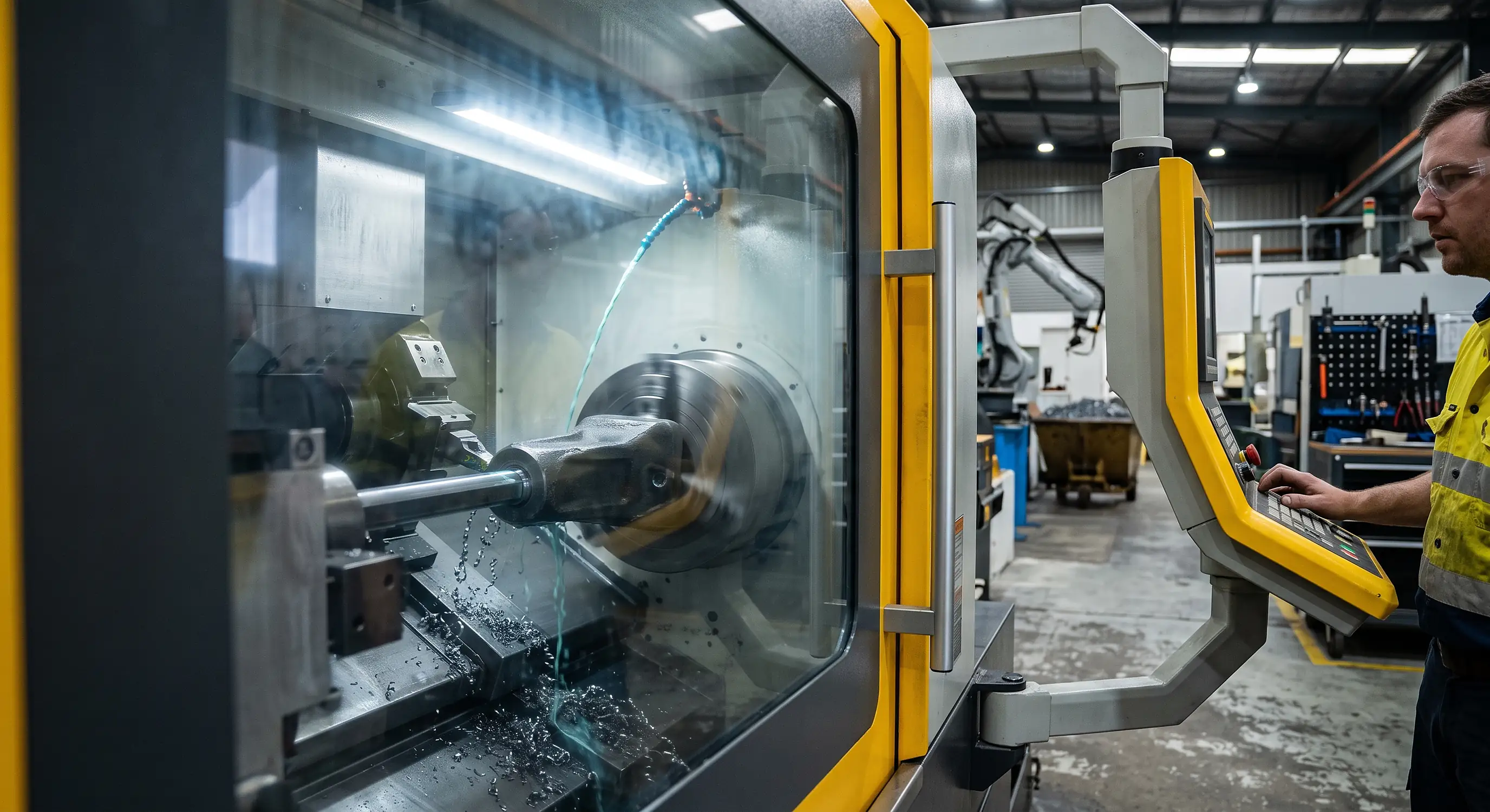
- Post-weld CNC milling and CNC turning to ±0.01mm on facing, boring, reaming, threading, and counterboring operations
- Match-machining of welded assemblies in a single setup
- Stress-relief coordination before finish machining on critical assemblies
- Emergency and rapid turnaround work: 24-hour prototyping capability for urgent replacement components and breakdown machining
- Quote within 4 business hours of receiving drawings or a sample
Fabricators who bring us metal machining work, from wear-critical steels through to routine mild-steel brackets, tend to stay with us because the same CNC machinist Melbourne team handles the drawing review, the machining, and the sign-off, rather than passing the job between departments. If you’re still weighing up machining partners more generally, our guide on finding a CNC machine shop that understands fabrication workflows covers what to look for before you commit. If you’re a fabricator or project engineer searching for a CNC machining Melbourne partner who already understands post-weld handoff work, our Mordialloc workshop is accessible from Dandenong, Clayton, Moorabbin, Braeside, and the broader SEMMA manufacturing corridor.
Call (03) 9587 0405 or request a quote or visit ssengineering.com.au to send drawings for review.