Introduction
The jump from a single validated prototype to a repeatable production run is one of the most underestimated transitions in the machining industry. A CNC machining centre that produces a flawless one-off part does not automatically produce flawless parts at volume. The physics change. Tool wear accumulates. Thermal drift compounds. Fixturing variation adds up. What worked for one part fails across a batch.
This is a process control problem, not a machine capability problem. Successful CNC manufacturing at scale requires design optimisation, statistical tolerancing, automated workholding, in-process metrology, and a quality management framework that catches drift before it produces scrap. In Australia, it also requires compliance with specific safety and quality standards that differ from international defaults.
This guide covers the CNC engineering fundamentals that product developers, procurement teams, and design engineers need to understand when moving CNC machined parts from prototype to production in the Australian market.
Summary
Key Takeaways
- Machine capability is not process capability. A CNC machine that holds ±0.005 mm on a single part may drift beyond tolerance over a 500-piece run. Scaling requires statistical process control (Cpk ≥ 1.33), not just tight-tolerance equipment (SixSigma.us, 2025).
- Optimise geometry before you scale. Thin walls below 0.8 mm in aluminium, unsupported height-to-thickness ratios above 15:1, and internal corner radii smaller than one-third of pocket depth all generate high scrap rates at volume (RapidDirect, 2026).
- Tolerances drive cost exponentially. Moving from ISO 2768-m general tolerances (±0.1 mm) to ±0.01 mm precision can increase per-part cost by 5–10x due to slower feeds, more inspection, and tighter environmental controls (ISO 2768; ISO 286).
- Zero-point workholding cuts setup time by up to 90%. Standardised fixture plates with pneumatic clamping modules achieve sub-5 µm repeatability and eliminate manual alignment variation between parts (RivCut, 2025).
- AI and closed-loop metrology are production-ready. In-process probing, adaptive feed rate optimisation, and digital twin simulation now detect and correct drift automatically during long CNC machining runs (CAPPS 2026; iFactory AI, 2025).
- Australian manufacturers must comply with AS/NZS 4024. Safety-rated interlocks, dual-channel emergency stops, and Performance Level-rated control systems are mandatory for CNC machinery operating in Australia (SafeWork NSW; WorkSafe Victoria).
1. Why Prototypes Do Not Scale Automatically
A prototype is a demonstration of machine capability — the theoretical best a CNC machine can achieve under ideal conditions. An operator takes time to set up the part, manually adjusts offsets, and may run the program at conservative feed rates to ensure success. The result is a perfect part, but it is a one-off achievement, not a repeatable process.
When output requirements move to hundreds or thousands of units, the variables that were invisible during prototyping become dominant. Tool wear changes cutting forces over a batch. Thermal expansion shifts dimensions across a shift. Clamping variation from manual vises introduces positional scatter. Chip evacuation behaviour changes with cycle time optimisation. These are not failures of the CNC machine — they are the normal physics of metal machining at volume.
The metric that matters is process capability, measured using the Cpk index. While machine capability (Cp) measures the theoretical spread of the process relative to the tolerance band, Cpk accounts for how well the process is centred on the target value. A Cpk of 1.33 or higher is the standard threshold for production-capable processes in precision CNC machining (SixSigma.us, 2025). Achieving this requires systematic elimination of variation — not just a good machine and a skilled operator.
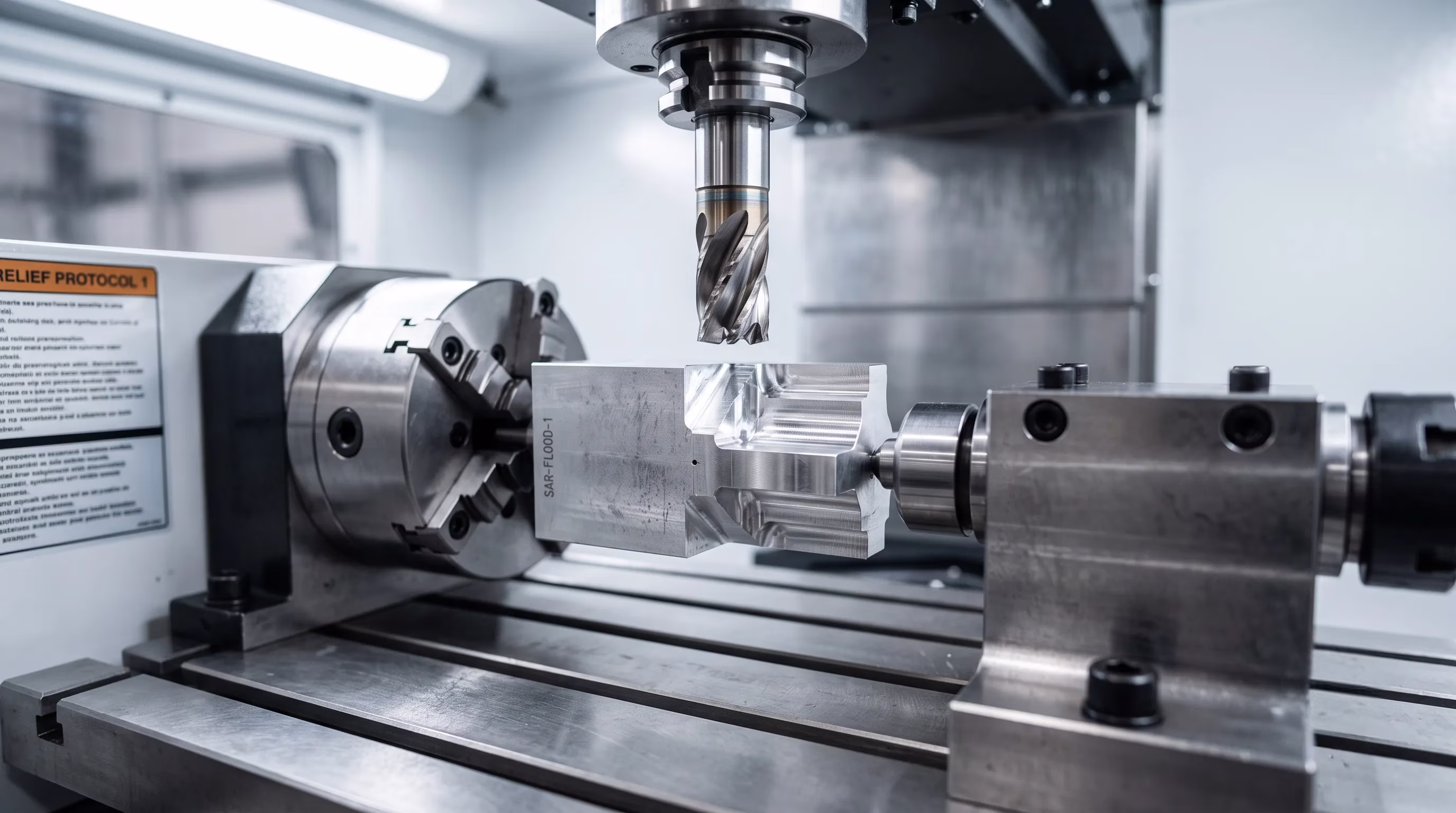
2. Design for Manufacturability: Geometry That Survives Volume
Geometries that are straightforward to machine in a prototype can generate high scrap rates and excessive cycle times at volume. Design for Manufacturability (DFM) review during the prototype phase is the single most effective way to reduce cost and risk when scaling CNC machining production.
Critical Geometric Limits
Standard CNC milling and CNC turning operations have well-established geometric limits that directly affect yield at volume. Minimum wall thickness for aluminium parts should be 0.8 mm; for steel, 1.2 mm. Internal corner radii should be at least one-third of the pocket depth to allow standard endmill engagement without chatter. Hole depth-to-diameter ratios beyond 10:1 require specialised tooling and slower feeds that significantly increase cycle time (RapidDirect, 2026; PREMSA Industries, 2026).
Thread depth should be limited to 1.5 to 3 times the nominal diameter — engagement beyond this provides negligible additional strength and increases tap breakage risk. Undercuts and internal features that require tool access from multiple angles add setups and fixtures, which multiply cost at volume.
Thin-Wall Machining Risks
Thin-walled geometries are particularly sensitive to scaling. Wall stiffness drops exponentially as thickness decreases, making parts susceptible to deflection under cutting forces, vibration-induced chatter, and clamping distortion. The universal upper limit for unsupported thin walls in high-volume production is a height-to-thickness ratio of 15:1. Exceeding this requires specialised fixturing, reduced cutting parameters, and often multiple light finishing passes — all of which increase cycle time and cost per part.
Structural ribs designed to support thin walls should have a thickness of 50–70% of the primary wall. Ribs thicker than this cause thermal warping and sink marks on the opposite face, particularly in aluminium alloys. These DFM rules apply equally to rapid prototyping and full production — the difference is that violations are exposed by volume, not by a single part.
3. Tolerancing for Production: ISO 2768, Fits, and Cost
Over-tolerancing is one of the most common cost drivers in CNC machining services. Every tolerance tighter than the functional requirement adds inspection time, reduces feed rates, requires more stable environmental conditions, and increases reject rates. The cost relationship is not linear — it is exponential.
ISO 2768: The Default Standard
For CNC machining Australia and international work, the default general tolerance standard is ISO 2768-mK, where ‘m’ defines the medium tolerance class for linear dimensions and ‘K’ specifies the geometric tolerance class. Under ISO 2768-m, a 50 mm dimension carries a general tolerance of ±0.1 mm. This is achievable with standard CNC milling and CNC turning setups at production speeds without extraordinary measures.
Moving to ±0.05 mm requires tighter process controls: temperature-controlled environments, more frequent in-process inspection, and slower feed rates. Moving to ±0.01 mm typically requires grinding or lapping as a secondary operation, CMM verification of every part, and climate-controlled metrology. The per-part cost can increase by 5–10x (ISO 2768; Yijin Solution, 2026).
ISO 286 Fit Classifications
For mating components, engineers specify fits using the ISO 286 hole-basis system. Clearance fits (H7/g6) allow free movement and are standard for non-critical assemblies. Transition fits (H7/k6) provide a slight interference suitable for locating pins and alignment features. Interference fits (H7/p6) require press assembly and are used for permanent shaft-hub connections. Specifying the correct fit class at the design stage avoids expensive post-machining adjustments during production ramp-up.
4. Smart Manufacturing: AI, Digital Twins, and Closed-Loop Metrology
The CNC engineering landscape in 2026 is defined by a shift from operator-dependent machining to data-driven, automated production. Smart manufacturing systems integrate hardware, software, and machine learning to detect and correct process variation in real time.
Cloud CAD/CAM and Digital Twins
Modern CAD/CAM platforms use machine learning to analyse part geometry and automatically identify potential manufacturing issues — thin walls, sharp internal corners, inaccessible features — before a tool path is generated. Once the process is optimised, it is validated using a digital twin: a virtual model of the physical CNC machine including its axis kinematics, power limits, and thermal properties. The digital twin simulates the entire machining cycle, detecting collisions, excessive forces, and thermal distortion before any material is cut (Coherent Market Insights, 2026).
AI-Native Controllers and Adaptive Feed Rates
On the production floor, AI-native CNC controllers analyse real-time sensor data — spindle load, axis vibration, thermal expansion — to optimise cutting parameters during the cut. On difficult-to-machine materials like Inconel and titanium, these systems adjust feed rates dynamically based on material hardness variations, reducing cycle times by 15–25% while maintaining consistent surface finish (iFactory AI, 2025). Tool wear monitoring systems track vibration signatures and motor current to predict tool failure, triggering automatic tool changes before a worn edge compromises part tolerance.
Closed-Loop On-Machine Metrology
To prevent quality drift over long production runs, modern machine shops integrate automated in-process probing directly into the CNC cycle. Metrology software compares measured dimensions against the CAD model after each operation. If a dimension drifts due to tool wear or thermal expansion, the system calculates and applies offset corrections to the controller automatically. This creates a closed-loop quality system that maintains Cpk targets without manual intervention (CAPPS 2026; ResearchGate, 2025). These capabilities are particularly valuable for high-volume machining and repetition engineering work where consistency across hundreds of parts is non-negotiable.
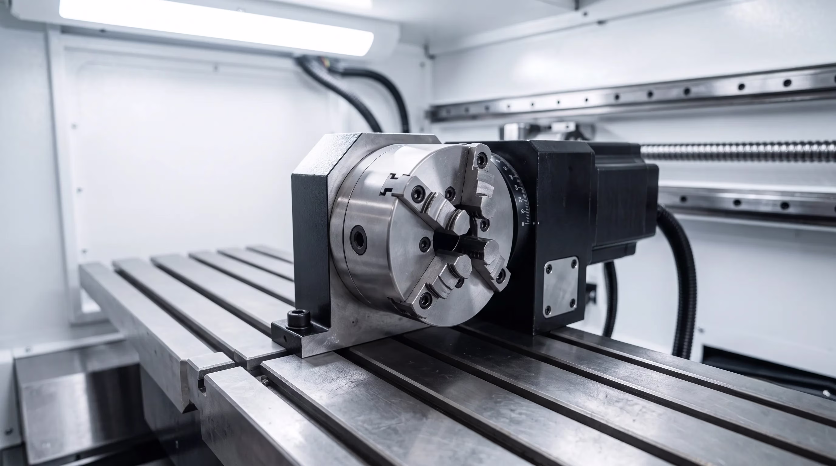
5. Workholding and Setup Reduction for Repeatable Output
Manual workholding is one of the largest sources of variation in CNC manufacturing. Differences in clamping force, part alignment, and datum location between setups introduce scatter that shows up as dimensional inconsistency across a batch.
Zero-Point Workholding Systems
To eliminate manual setup variation, production facilities use zero-point workholding systems. Parts are mounted on standardised fixture plates offline, then loaded onto receiver modules permanently fixed to the machine table. Pneumatic clamping locks the plate in position in under 10 seconds with sub-5 µm repeatability. This applies the Single-Minute Exchange of Dies (SMED) methodology to the CNC environment, reducing setup time by up to 90% compared to conventional vise-based workholding (RivCut, 2025).
Clamping forces range from 10 to 40 kN per module, ensuring rigidity under heavy CNC milling loads. Premium systems include elastic collet compensation that absorbs minor centre-distance deviations and thermal expansion of the fixture plate. High-end production systems achieve over 100,000 clamping cycles without loss of reference precision.
Palletised Automation
When combined with robotic pallet loading, zero-point systems enable continuous unattended machining. The robot loads pre-fixtured pallets while the machine cuts, eliminating spindle idle time between parts. This is the standard configuration for high-volume machining production runs in modern CNC machining Melbourne workshops and across CNC machining services manufacturer facilities nationally.
6. The Australian CNC Manufacturing Landscape in 2026
The Australian machining industry is undergoing a structural shift driven by rising operational costs, energy price volatility, and government investment in sovereign manufacturing capability. Domestic CNC machining services are moving away from low-cost commodity work toward high-mix, high-trust production where quality systems, traceability, and local responsiveness justify the cost premium.
Economic Context
Manufacturing contributes approximately $115 billion annually to the Australian economy and employs over 850,000 people (Ai Group, 2025). However, domestic manufacturers face labour costs 2–3x higher than Southeast Asian competitors and energy costs that have risen significantly since 2022. To offset these structural costs, Australian CNC machining Australia shops are investing heavily in automation, 5-axis machining centres, and simulation-first workflows that maximise spindle utilisation and minimise downtime.
Industry Support and Training
Peak bodies like the Australian Manufacturing Technology Institute Limited (AMTIL) and the Advanced Manufacturing Growth Centre (AMGC) support the transition through technology promotion, co-investment in commercialisation projects, and export facilitation. Regional alliances — such as the Australian Aerospace Alliance and the Special Vehicle Alliance — allow small and mid-sized machining manufacturers to collaborate on contracts that individually exceed their capacity. On-site training centres at leading machining Australia facilities are addressing skill shortages by developing the next generation of CNC programmers and operators.
7. Machine Safety Compliance Under AS/NZS 4024
Operating CNC machinery in Australia requires compliance with the AS/NZS 4024.1:2019 series of safety standards, enforced at state level by bodies such as SafeWork NSW and WorkSafe Victoria. The series contains 26 parts covering hazard identification, control system design, guarding, interlocking, and emergency stop systems.
Key Requirements
Safety logic must be separated from standard CNC or PLC operating systems so that software faults cannot compromise safety functions. Emergency stops must use dual-channel, safety-rated circuits that actuate a deterministic stop across all axis drives and spindle systems. Movable guard doors require monitored interlock switches, and where spindle residual motion persists after power removal, guard locking devices must prevent door opening until motion has ceased.
Physical guards must be positioned at safety distances calculated under AS/NZS 4024.1801 to prevent operator reach into operating zones. For Australian fabrication companies and machine shops running CNC machining and CNC mill Australia equipment, these are not optional — they are legally mandated.
Retrofit Requirements
Because full machine replacement is capital-intensive, many Australian manufacturers retroactively upgrade legacy machines to current AS/NZS 4024 standards. Typical retrofit packages include safety-rated PLCs, monitored guard interlocks with locking devices, light curtains and safety mats for access zones, and dual-channel emergency stop circuits. A competent safety assessment under AS/NZS 4024.1201 must be completed before and after any retrofit to verify compliance.
8. How Southside Engineering Scales Your Parts
As a CNC machining services manufacturer based in Melbourne, Southside Engineering has been helping Australian businesses move from prototype to production since 1973. We understand that scaling is not about running the same program faster — it is about building a repeatable process around your part.
We review your design for manufacturability before quoting. We apply ISO 2768-mK tolerancing unless your specification requires tighter. We use standardised workholding systems to eliminate setup variation across batches. And we run in-process inspection to catch drift before it becomes scrap. Whether you need ten rapid prototyping units or ten thousand repetition engineering parts, the process is the same: controlled, measured, and documented.
Our Mordialloc workshop runs CNC machining, CNC milling, CNC turning, high-volume machining, and assembly and production across aluminium, stainless steel, carbon steel, brass, bronze, copper, and engineering plastics. We work with defence, mining, construction, general manufacturing, and fabrication companies. If you are searching for CNC machining near me, CNC machine Melbourne, reliable CNC machine services, or an experienced CNC machinist Melbourne for production scaling, we are 100% Australian owned and ready to quote.
Ready to scale your CNC machined parts? Get a quote or call us on (03) 9587 0405.